Hey o/
This project follow the Matrix Camera's project. It was the initial inspiration for this project.
Following a user's cursor to add some feedback, like a firework or something that destroys the screen, is a fun thing to integrate into a website. And I think that ASCII representation is also a fun thing. Combining both should be, theoretically, the funniest thing ever.
With this in mind, the question that follows is: What shape should the ASCII be, and how should it be implemented? The first part had an obvious answer: as I wanted to use it on the front page of my website, it should be a 3D representation of myself, looking at the mouse cursor. Answering the second part of the question, however, is a little trickier.
When trying to represent an object in ASCII, we face one major problem: ASCII art isn't a 3D representation and cannot 'face' something. The solution I decided to use was to render a 3D Object, but, instead of pixels during the rendering, try using ASCII characters.
The first step I took during this project was to figure out how I wanted to structure my 3D object. At first, I wanted to just save vertex positions and have a list of vertices for each triangle. Doing so would allow me to recreate a mesh, which would be good enough for this project. Unfortunately, I quickly realized why 3D software also uses normals, as they help with back-face culling. This should also help in the case of lighting and shadow. The final structure I decided to use for the object is this one:
3D Object
    > Points [x,y,z] (Vertices)
    > Triangles [A,B,C]
    > Norms [x,y,z]
    > Axe
Axeis the x, y and z axis, that will help to save any rotation I have already done on my object.
Talking about rotation, the next thing I tried to implement was being able to rotate these vertices. However, rotation in 3D space isn't as easy as rotating something in 2D space, due to the fact that if you rotate something on an angle, you can easily lose a possible axis of rotation. This is called Gimbal Lock.
 Illustration by Julian Zeitlhöfler
To avoid this situation, we need to use rotation quaternions, which are defined by an angle of rotation and a unit vector, then apply them to all the vertices we have. I will not bore you with math equations, as I do not think they are relevant here, but I will note that I did have some difficulty with the matrix multiplications needed to rotate a quaternion (v'=q*v*q^-1). This difficulty was principally due to the fact that math wasn't fresh in my mind, and I needed a reminder.
At this point, I still didn't have any visual clue of what was happening and solely used console.log to see if the points were moving in the way I wanted. To help me settle this, I decided to use a <canvas>, where I would draw the lines between the different vertices of my triangles, to help me understand what was happening to my object.
Projecting a 3D object into 2D space can be done by two means: Parallel projection or Perspective projection. The second one being harder to implement, I decided to focus on the first one, and, to be precise, to use an Orthographic projection. I also decided that my camera would be facing -Z, allowing me to simplify the projection to just positioning a point (x,y,z) at the new coordinates (x,y) without any calculations.
To help me understand what was in front and what was in the back, I also decided to add a succinct way of doing back-face culling, by removing every triangle that had a negative Z normal (This is the point where I added the normals into my 3D Object).
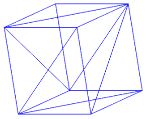 Orthographic projection of a cube
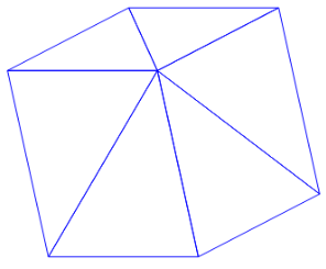 Same cube with back-face culling
I finally added a simple function to follow the mouse movement, applying a sigmoid function to the distance from the center, and rotating the cube to follow the cursor.
When all this setup was finally done, and with this cube following every one of my movements, it was finally time to see some ASCII. But how? To do so, we will use rasterisation. To simplify it, it's like looking at something and deciding which pixels are turned on and which pixels are turned off. But, instead of pixels, we will turn on ASCII characters, or a space if it should be turned off.
To rasterize a 3D object, we will first need to select all the triangles that can be seen by the camera. This is done by Back-face Culling, for which we already have an implementation, succinct as it is (I did implement a more complex way later on, by calculating the dot product between the triangle's normal and the view direction, when trying to solve another problem). When we know which triangles we want to rasterize, we need to check for each pixel if it is inside the triangle or not.
Checking if a pixel is inside a triangle can be done using barycentric coordinates. This will also help us determine which vertices of the triangle affect this pixel the most (Which will be used when applying texture). Calculating the barycentric coordinates will be done using dot products. If the sum of these coordinates equals 1 or less, we are in the triangle. If not, we are out. After that, we can calculate the zBuffer, which helps us understand which triangle is in front of the others, to only show the one in the front.
But now, we need to add texture to this triangle. And to do so, we will again use the barycentric coordinates that we just calculated to see, in a texture triangle, which color I should pick. Which means we need to update our 3D Object, as it needs to have a UV Map, which is a projection of those triangles onto texture positions. I also added a texture object.
3D Object
    > Points [x,y,z] (Vertices)
    > Triangles [A,B,C]
    > Norms [x,y,z]
    > Axe
    > UV Points
    > UV Triangles
Texture
    > Size
    > Color
As we don't have a way to represent color in ASCII art (without transforming it into the disgusting ANSI art), I just decided to use grayscale textures (I could have calculated it depending on the formula y = 0.2126*r + 0.7152*g +0.0722*b, but you know, not worth it)
Technically, the initial objectives were now complete. I could draw a 3D object with a texture and turn it toward the mouse. However, to simplify my changing whims, I decided to implement a way to parse a Wavefront .obj file and a texture file. With this, I could just create an object in Blender, triangulate it, and draw a texture before importing it into my ASCII Engine.
.Obj files are quite straightforward, which explains why I chose them. You have lines for the geometric vertices v, the texture coordinates vt, the vertex normals vn, and a way to link all of that, the faces f. There is the possibility to have more data parsed into them, but I didn't need it in my case.
The parsing of the texture was also quite straightforward; I just needed to go through each pixel and populate my texture object with the data.
As of the time I'm writing this, there are quite a few improvements I can see for this engine. I may challenge myself to resolve them, and they may be outdated by the time you are reading this.
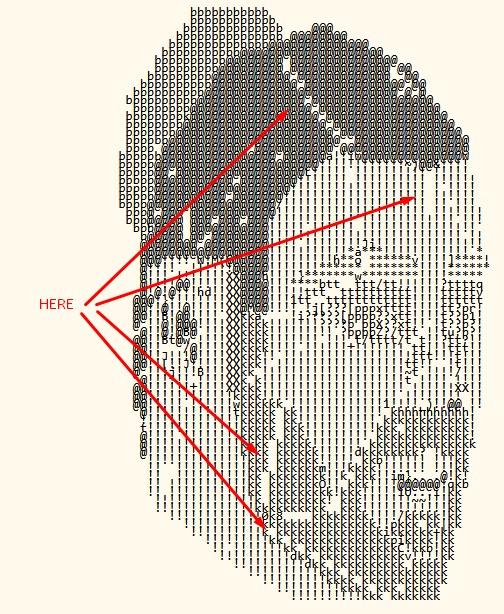
For now, it seems that the calculations for the edges of my triangles are not working properly, as you can sometimes see white lines at the edges of my triangles. I would like to tackle this problem to ensure a seamless experience.
Orthographic projection is a good way to implement things quickly and to have a visualization of the 3D elements. However, it also easily deforms the different objects, and I would love to have a perspective projection to ensure a more realistic view.
This will also allow me to play with matrices, as I would need to implement projection matrices onto my vertices.
The final step that I can see in this project would probably be to add lighting and shadow, as it would allow the experience to be more immersive. But for now, I absolutely don't know how it could work, so it could be a nice challenge ;)

